What Are the Best Cylindrical Fenders in 2026?
What makes a cylindrical fender the best choice in 2026? Usually, it is not the product with the largest dimensions or the lowest quoted price. Fit matters. UNCTAD’s Review of Maritime Transport 2024 reports that over 80% of global trade by volume is carried by sea. That scale makes reliable berth protection a practical concern for ports, terminals, and vessel operators.
Cylindrical Fenders are used in varied settings, from quay walls and dolphins to vessel sides and workboats. Their simple shape can support flexible installation, but performance depends on more than appearance. PIANC’s Guidelines for the Design of Fender Systems emphasizes assessing berthing energy, reaction force, hull pressure, and site conditions when designing a system. A useful comparison should therefore consider fender dimensions, rubber compound, reinforcement, mounting method, expected vessel approach, and maintenance needs. Small differences matter. A tight tidal range, exposed berth, or uneven contact surface can change what works in practice.
This guide examines the leading cylindrical fender options for 2026 through those application-focused criteria, rather than treating one model as universally superior. It also considers product documentation, manufacturer experience, and the availability of technical support. A specification sheet can look convincing and still leave questions unanswered. Buyers should confirm design assumptions with qualified marine engineers and request project-specific performance data before selecting a system. No shortlist can replace that review. The right fender is the one suited to the berth, the vessel, and the operating conditions—not simply the one with the boldest claims.
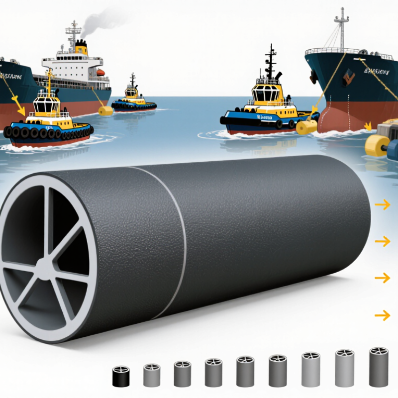
Cylindrical Fenders Explained: Rubber Body, Bore, Length, and Mounting
A cylindrical fender’s rubber body, bore, length, and mounting all affect how it cushions contact. The bore is not just an empty center: changing its diameter changes the rubber wall and can alter stiffness and compression. Ask for tested energy-absorption and reaction-force curves for the exact size and compound. Appearance alone tells you little.
PIANC’s MarCom Working Group 33 Fender Guidelines (2002) frame selection around berthing energy, including vessel mass and approach speed. For scale, a 5,000-tonne vessel at 0.15 m/s has about 56 kJ of basic kinetic energy before effective-mass and other design factors are applied. This is an illustration, not a final sizing value. Real conditions matter. A longer fender spreads contact along the hull, while the mounting must resist pull-out, wear, and repeated impact. Check the available clearance and backing structure, not only the fender length.
In practice, compare the expected reaction force with the quay’s capacity, then confirm the fender can absorb the design energy. Inspect for cuts, hardening, and uneven compression; small damage can be easy to miss. Still, this is an imperfect shortcut: vessel conditions and installation details can change the result, so a site-specific review is worth doing.
Choosing a Cylindrical Fender in 2026: How Bore Affects Rubber Cross-Section
The chart compares the geometric rubber cross-sectional area for three example cylindrical-fender dimensions. Area is calculated from the outside diameter and bore; it is not an energy-absorption or reaction-force rating.
Example dimensions are shown in outside diameter × bore × length (mm). Actual performance depends on the rubber compound, fender geometry, compression, and installation. Check the required mounting arrangement and available clearance when selecting a fender.
How Performance Is Measured: Energy Absorption (kN·m) and Reaction Force (kN)
For cylindrical fenders, energy absorption and reaction force describe different parts of the same impact. Energy absorption, measured in kN·m, is the work the fender can take in as it compresses. On a test graph, it corresponds to the area beneath the force-versus-deflection curve. Reaction force, measured in kN, is the load passed back to the vessel and berth during compression. One value measures absorbed impact energy; the other helps show how hard the fender pushes against nearby structures.
Numbers need context. A fender rated for high energy absorption may also produce a reaction force that exceeds the berth’s design limit. Compare performance at the same deflection and under the same test conditions, including temperature and loading rate. Then check whether the stated figures apply to one fender or an entire installation. Real berthing is rarely perfectly square: a vessel may contact at an angle, and pressure can concentrate near one edge. That detail matters. Ask for the full force-deflection curve, not only two headline ratings. It gives engineers a clearer basis for matching fender capacity to vessel energy and allowable structural load, though field conditions can still differ from the test.
Apply PIANC WG33 Berthing-Energy Guidance to Match Fenders to Vessels
PIANC WG33 guidance starts with berthing energy, not a fender catalogue. Estimate the vessel’s displacement and approach speed, then account for factors such as added water mass, eccentric contact, and berth geometry. Because energy rises with the square of speed, a small change in approach velocity can matter greatly. Small details matter.
For a cylindrical fender, compare its verified energy absorption and reaction force with the design case. Check that the reaction will not overload the quay structure or create excessive pressure on the vessel’s hull. Fender spacing matters too: a vessel may contact between units, especially when it arrives at an angle. Real calls vary.
Use operating records where available, and test assumptions against the largest design vessel and credible approach conditions. Consider tide range, hull shape, and the fender’s compression limits. A tidy spreadsheet can still hide a poor assumption, particularly when approach speed is guessed rather than measured. WG33 provides a disciplined framework, but site data and engineering review turn that framework into a defensible selection.
What Are the Best Cylindrical Fenders in 2026? - Apply PIANC WG33 Berthing-Energy Guidance to Match Fenders to Vessels
Illustrative screening comparison: Vessel displacements and berthing speeds below are representative planning assumptions, not prescribed PIANC values or data for specific vessels. Uncorrected kinetic energy is calculated as E = ½ × displacement × berthing speed²; with displacement in tonnes, the result is in kilojoules. The screening energy applies an assumed 1.5 multiplier for illustration only. This multiplier is not a PIANC WG33 standard correction factor.
| Representative vessel class | Illustrative displacement (t) | Normal berthing speed (m/s) | Uncorrected kinetic energy (kJ) | Illustrative screening energy (kJ) | Cylindrical-fender selection checks |
| Coastal workboat | 2,000 | 0.20 | 40 | 60 | Check hull contact height, fender spacing, local hull pressure, and whether one or more units share the berthing load. |
| General cargo vessel | 10,000 | 0.15 | 113 | 169 | Verify rated energy absorption at the permitted deflection and confirm reaction force is within the quay and vessel limits. |
| Container feeder | 25,000 | 0.15 | 281 | 422 | Assess the full range of contact elevations, fender-panel or chain details if used, and the effect of berthing angle. |
| Bulk carrier | 60,000 | 0.12 | 432 | 648 | Check the governing loaded and ballast conditions, berth geometry, fender-unit load sharing, and allowable structural reaction. |
| Large tanker | 150,000 | 0.10 | 750 | 1,125 | Use a site-specific berthing analysis; verify energy capacity, maximum reaction, deflection clearance, and performance at the project temperature. |
PIANC WG33 application: Treat these figures as an initial comparison, not a final fender design. A project calculation should establish the design vessel and berthing conditions, then account for relevant effective-mass, eccentricity, berth-configuration, softness, and other applicable factors. Select cylindrical fenders using verified performance data at the specified deflection and temperature, and check both energy absorption and reaction force against the vessel and berth limits. Final sizing and layout require site-specific engineering review.
2026 Selection Criteria: Check Compression Curves, Hull Pressure (kPa), and Fit
In 2026, compare cylindrical fenders by their compression curves, not diameter alone. A force–deflection curve shows how reaction force rises as the fender compresses; the area beneath it represents absorbed energy. PIANC’s 2002 Guidelines for the Design of Fender Systems treats energy absorption, reaction force, and hull pressure as linked design checks. Ask for test curves at the proposed temperature and compression range. A single peak-force figure hides useful detail.
Hull pressure is usually calculated from reaction force divided by the effective contact area, then checked against the vessel’s allowable pressure. That area can shrink on a curved hull or with poor alignment, raising local pressure. There is no universal safe kPa limit for every vessel. Request the calculation, assumed contact patch, and design margin. Also verify actual clearance, mounting, and fender length against the berth drawings. ISO 17357-1:2014 covers high-pressure pneumatic fenders, so it should not be treated as a performance specification for solid cylindrical fenders.
Tips: Fit matters. Measure the gap at the lowest operating tide, then check whether the fender can compress without bottoming out. Ask for the complete curve and test basis, not just a catalog value. Small caveat: drawings can miss real hull curvature. Review the fit with vessel-specific dimensions.